
To assess the impact of pseudo-conformal geometry in the irradiative pattern of a K-Band antenna array, a three-waveguide array was designed that allows the forward displacement of the outer waveguides in relation to the central element. The field pattern of the antenna array for different geometric configurations was simulated using the correct excitation reaching the individual waveguide through the beamformer. The variation in the number of beams, beamwidth of the main beam, and separation between beams with displacement distance of the external waveguides were calculated. Comparison of the simulated pattern with measurements is presented for this antenna to verify the accuracy of the radiation model.
Introduction
A conformal antenna is one in which either the single antenna is shaped or an array of antenna elements are placed on a curved surface. Such antennas are found in modem aircraft, radar altimeters, satellite communications and surveillance radars where aerodynamic integration with the airborne vehicle is needed [1]. Other possible uses of a conformal antenna are in terrestrial applications, since the antenna designer can use the geometric shape as another degree of freedom to beamform the irradiative pattern.
In a conformal antenna, the antenna elements are placed tangential to the curved surface. Typical geometries are cylindrical, spherical, and ellipsoidal. For this study, we concentrate on a convex semicircle. The use of a waveguide as an antenna element facilitates the construction of the array due to the small size and facility of packaging in a wooden structure with openings big enough to fit the waveguide. It has the disadvantage of being a poor radiator having low directivity. Despite this limitation, a waveguide as a probe can be found in many applications. For instance, waveguide arrays have been used in the measurement of dielectric properties of biological tissues [2].
To use a waveguide in a perfect conformal arrangement such as a convex semicircle would be a rather bulky assembly. Having all the waveguides arrayed in a parallel way offers a more compact and sturdy assembly but the apertures of the waveguides will not be tangential to the circle line. The pattern of an array depends not only on the type of antenna element but also on the separation between the elements that make the array. For a conformal surface, the geometry is not planar. The purpose of this work is to quantify the variation in the antenna pattern due only to the non-planar geometric characteristic. The study is done for a circular geometry, in which the antenna elements are not quite tangential to the surface. This fact facilitates the construction of a rugged antenna assembly. In this study we do not quantify the differences with an equivalent antenna structure with the elements placed tangential to the surface, as may be the case in a perfect conformal antenna.
Radiated Field for three waveguides separated by a fixed distance
For the pseudo-conformal antenna, the waveguides are inserted into a wooden structure with holes equal in size to the dimension of the waveguides (13mm x 6mm). The waveguides are separated at a fixed distance approximately three times the wavelength. The waveguides can be displaced parallel to each other such that either the waveguides at the edges or in the central location can be protruded. For the array on a conformal surface, the three waveguides were placed tangential to a semicircular wooden structure having a radius such that the linear displacement of the outer waveguides in relation to the central waveguide will be the same distance as in the pseudo-conformal case.
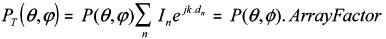
The total field of the antenna array is the contribution of the field pattern radiated by the individual antenna elements that integrate the array.
where Pn is the radiated field pattern of the antenna element n, In the excitation input, k is the vector in the direction of the observer, dn the distance from the origin to the antenna element n. In rectangular coordinates,
For identical antenna pattern
Parameter Variation with Protruding Distance
The testing of the waveguide array for different geometries was done in an anechoic chamber using a hom antenna on the transmitter side at 18 GHz. The field pattern of the pseudo conformal geometry array was measured for a) planar and b) the outer waveguides displaced 1, 2, and 3 cm forward.
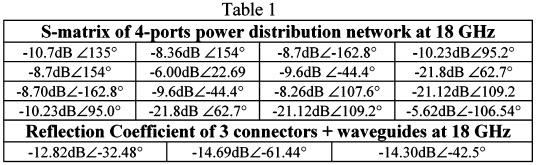
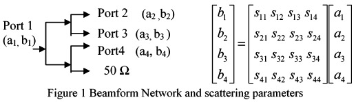
For the analysis of the effect of the geometry on the antenna parameters, it is desirable to have the same excitation in all the waveguides. We used three T-junctions and equal length coaxial cables connected between T-junctions. The unused port of one of the T-junctions is connected to a matching load as is shown on Figure 1. The waveguides with similar response were selected for the antenna assembly. Nevertheless, some differences are to be expected among the waveguide inputs due to the imperfection of components and the construction of the cables. The S-parameters of beamformer network were measured in an Agilent Network Analyzer Model E8364B proceeding two ports at a time and having a matching load in the other three ports. Table 1 shows the S-matrix values of the beamformer network. Figure 1 shows the measured SII for the connector waveguide assembly at 18 GHz.
Using the reflection coefficient r, we can substitute a2, a3, and (4 by b2r 2, b3r3, and b4r 4. Rearranging terms, we found the terms b2, b3, and b4 as a function of at, which are the actual waveguide excitations, or 11, 12, and 13. The mathematical description of the waveguide pattern was taken from [3]. The comparisons between the simulation and measurements for the H-plane are shown on Figure 2.
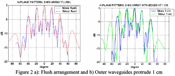
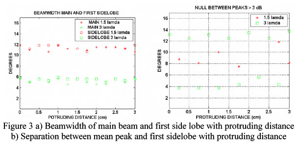
Figure 3 and 4 show the effect of displacing the two outer waveguides forward in relation to the central waveguide on the pattern. The beamwidth variation is within 2 degrees. The variation of the width of the null can reach up to 8 degrees in the case of waveguides separated approximately 3 wavelengths.
Conclusions
The conformality or spatial arrangement of the antenna components can be used as another degree of freedom in the design of multibeam antennas. The beamwidth of the main lobe and sidelobes, the width of the null region between the central beam and adjacent beam, and the number of beams are all affected by the protruding distance of the antennas in the array. This is due to the constructive and destructive summation of the individual antenna beams in the far field due to the additional delay caused by the protruding distance.
References
[1] L. Josefsson and P. Persson, “Conformal Array Antenna Theory and Design” IEEE Press 2006.
[2] Foti, S. J., R. P. Flam, J.F. Aubin, L.E. Larsen, J. H. Jacobi, “A waterImmersed Microwave Phased Array System for Interrogation of Biological Target”, Medical Applications of Microwave Imaging, book edited by L. E. Larsen and J. H. Jacobi in IEEE Press 1986.
[3] Johnson R. C., Antenna Engineering Handbook, McGraw-Hill Professional, 1992