Submit: (1) all code you wrote (not generated or provided files) including verilog hardware, verilog testing, matlab, etc. (2) other requested items such as diagrams etc.
Upload a single pdf to https://canvas.ucdavis.edu/.
Place all of your answers and code into a single pdf file with all problems and material in order (i.e., problem 1, problem 2,...).
Add titles to pages and file names so it is clear to which problem they belong. For example, Problem 1, prob1.v, prob1.vt,...
Diagrams. If a problem requires a diagram, include details such as datapath, memory, control, I/O, pipeline stages, word widths in bits, etc. There must be enough detail so that the exact functional operation of the block can be determined by someone with a reasonable knowledge of what simple blocks do. A satisfactory diagram may require an extra-large sheet.
Verilog. If a problem requires a verilog design, turn in copies of both hardware and test verilog code.
a table printed by your verilog testbench module listing all inputs and corresponding outputs,
a simvision waveform plot which shows (labeled and highlighted) corresponding inputs and outputs, or
verilog
test code which compares a) your hardware circuit and
b) a simple
Golden
Reference circuit (using high-level functions such as "+").
Include two copy & paste sections of text from your
simulation's output (one section showing a large number of passes,
and one small section showing where you purposely make a very
small change to either your designed hardware circuit or your
reference circuit to force the comparison to fail). It should look
something like this:
input=0101, out_hw=11110000, out_ref=11110000, ok
input=0111, out_hw=11110001, out_ref=11110001, ok
...
input=0101, out_hw=11110000, out_ref=11110001, Error!
...
For 1 and 3, the output must be copied & pasted directly from the simulator's output without any modifications.
In all cases, Show how you verified the correctness of your simulation's outputs.
Keep "hardware" modules separate from testing code. Instantiate a copy of your processing module(s) in your testing module (the highest level module) and drive the inputs and check the outputs from there.
Your verilog must implement hardware and be cleanly synthesizable, and follow guidelines in the verilog handouts. For example, having a for loop in your "hardware" verilog will result in an automatic 80% reduction in points since the verilog is therefore not implementing hardware.
Synthesis. If a problem requires synthesis, turn in copies of the following. Print in a way that results are easy to understand. Delete sections of many repeated lines with a few copies of the line plus the comment: <many lines removed> .
The "always @(*)" verilog construct may be used.
Run all compiles with "medium" effort. Do not modify the synthesis script except for functional purposes (e.g., to specify source file names).
Functionality. For each design problem, clearly state: 1) whether the design is fully functional, and 2) the failing sections if any exist.
Point deductions/additions. TotalProbPts is the sum of all points possible.
[Up to TotalProbPts × 50%] point reduction for not plainly certifying/showing that your circuit is functionally correct. This sounds drastic but you should have checked the correctness of your circuits' outputs anyway, it is impractical for the grader to check every result of every submission by eye, and thus an un-certified design will be treated like a marginally-functional design after a cursory glance at the hardware. In the worst case if there is no indication a design works at all, zero points will be given.
Following is an example of a fine way to certify correctness, if the "Y/N" is written either a) by hand individually for each test or b) automatically with a golden reference checker; but not printed automatically without individual checking.
            inA       inB    outExp  outMantissa     I Certify Correct
          -------- --------  ------ --------------   -----------------
          10101100 00110101  110010 01100110100101           Y
          00000101 10110101  101010 01010101010101           Y
          01010100 11101010  010100 11010101100101           no   // this indicates I recognize there is an error here
Clarity. For full credit, your submission must be easily understandable and well commented. Print code and CAD reports using a mono-spaced font (e.g., Courier) and a small size such as 9 point.
Total: 375 points
1. [90 pts] This problem requires the design of a block which calculates tan(θ) for a given θ, every clock cycle. Theta ranges from 0 to slightly less than π/4, or 45°. The latency may be as many cycles as needed.
theta input
12-bit fixed-point unsigned where:
0000_0000_0000 = 0.000 radians, and
1111_1111_1111 = π/4*(4095/4096) radians
out output
is 16-bit fixed-point 2's complement.
For each of your two designs, submit (a) through (d) below. When submitting the verilog file of your large lookup table, print only the first ~25 lines and the last ~25 lines and insert the comment "<Many lines removed>" for lines you deleted.
d) [45 pts] Synthesize your design at the following three cycle time values and report the 1) achieved cycle time (and corresponding clock frequency) and 2) area for each:
a very long cycle time, e.g., 1 ms (1 KHz), to find the minimum area;
a very short cycle time, e.g., 0.1 ns (10 GHz), to find the minimum cycle time;
a synthesis run with the cycle time set to the result from part (d)(2) multiplied times 1.5
Points for (c) and (d) are possible only if the design is fully functional and without synthesis errors or serious warnings.
[285 pts] The Alexnet convolutional neural net is widely credited with the dramatic rise in popularity of neural nets. Read the 2012 Alexnet paper paying particular attention to Sections 1, 2, 3.4, and 3.5. This project consists of building and synthesizing custom hardware for the first convolutional layer of Alexnet using a reduced image size. The primary specifications for this simplified project are as follows:
input image size of 35 pixels x 35 pixels x 1 grayscale "color". Each pixel is an 8-bit unsigned integer.
filter size of 11 pixels x 11 pixels. Each filter coefficient is an 8-bit 2's complement integer.
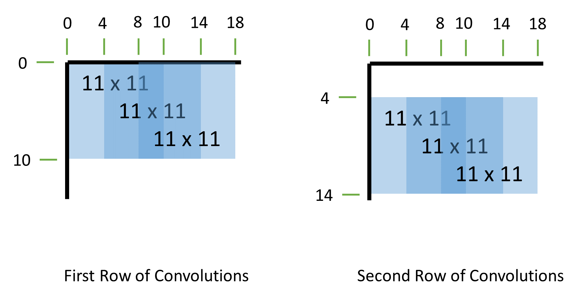
49 2-dimensional 11 x 11 convolutions total with a stride of 4 pixels in each direction for each convolution. The first 3 convolutions of the first two rows are shown in the figure below.
the output of each convolution is passed through a ReLU rectified linear function max(0,x).
a Max Pooling (article showing non-overlapped pooling) calculation with s = 2 and z = 3 (overlapped) is performed on the output of the ReLU calculations for which you have all the necessary data (9 outputs).
The testing environment is built as follows:
the testbench performs the following steps in order one after another:
For the first few samples of both the pixels and filter, use multiple combinations of 0 and +1 (for both pixels and filter coeffs), –1, –128 and +127 (for filter coeffs), and +255 (for pixels), to check calculations quickly.
See the "verilog: example code" web page for example code. Use random seed "123".
all pixel data, filter data, and outputs are printed to a *.m file for analysis in matlab.
Other requirements:
all convolutions should be calculated in approximately 539 clock cycles.
ReLU and max pooling calculations must be overlapped with convolutional calculations as much as is easily achievable
use only single-ported memories (modeled by verilog memories with a single address bus for both reads and writes)
You may use "signed" wires and regs for signed data calculations
use "*" for multipliers, and "+" for all adders.
Because synthesis times will be too long (approx 30 minutes) if all memories are synthesized, place all memory modules outside the top-level processor, registering values immediately before leaving and after entering the main module.
Minimum pipeline stages: convolution processor (2 stages), ReLU (1 stage), Max pooling (1 stage)
Submit the following.
a) [25 pts] A bulleted list and a few sentences describing your design including such features as: the number and size of memories, number of multipliers and adders, exact number of cycles to complete all convolutions, number of pipeline stages, in what order are the pieces and in what order are the convolutions calculated, etc.
b) [25 pts] Detailed pipelined block diagram with all functional details.
c) [25 pts] Detailed timing diagram showing the timing of the various processing units
d) [75 pts] Results for all convolutions printed by your verilog testbench.
e) [50 pts] Matlab copy and pasted output showing whether your design matches the matlab model or not. Your hardware must exactly match the output of the alex35.m matlab model.
f) [75 pts] Synthesize your design at the following three cycle time values and report the 1) achieved cycle time (and corresponding clock frequency) and 2) area for each:
a very long cycle time, e.g., 1 ms (1 KHz), to find the minimum area;
a very short cycle time, e.g., 0.1 ns (10 GHz), to find the minimum cycle time;
a synthesis run with the cycle time set to the result from part (f)(2) multiplied times 1.5
g) [10 pts] Report the number of clock cycles between the go signal and 1) the first output, and 2) the final output.
Points for (e), (f), and (g) are possible only if the design is fully functional and without synthesis errors or serious warnings.
Hint: See the Synthesis handout for details on the achievable cycle time and reading synthesis timing reports.
Hint: See the "matlab: tips for 281" web page for suggestions on addressing memories in matlab.
2025/03/04  Posted
2025/03/05  Added max pooling reference link
2025/03/10  Clarified test pixel and filter samples
2025/03/12  Changed image size from 31x31 to 35x35 to give 9 outputs instead of 4.
2025/03/18  Fixed typo, removed "fourth" from problem 2(g)(2)