Use your own algorithm, or try one that works like this:
-
For this discussion, "power of two" means both +2^k and –2^k where k is some integer.
-
Assuming the number is not a power of two (trivial solution), start with the powers of two just smaller and just larger than the input number. For example, if the input is 56, consider 32 and 64. Note the following matlab commands and results:
log2(56) → 5.8074
ceil(log2(56)) → 6
floor(log2(56)) → 5
abs(–56) → 56
-
Choose whichever number is closer. In this example, choose 64.
-
Subtract that power of two and repeat the procedure with the new number until the remainder is reduced to zero. For example, choose 56 – 64 = –8 so now use –8.
a) [25 pts] Write the described function in matlab.
b) [5 pts] Assuming your function is called numppterms(), run
the following bit of matlab code (a few points need fixing), submit the
figure, and report the Total Sum for all numbers 0.5 – 100.00 .
   StepSize = 0.25;
   NumTermsArrayPos = zeros(1, 100/StepSize);    % small speedup if init first
   for k = StepSize : StepSize : 100,
      NumTermsArrayPos(k/StepSize) = numppterms(k);
   end

   fprintf('Total sum = %i\n', sum(NumTermsArrayPos));

   figure(1); clf;
   plot(StepSize:StepSize:100, NumTermsArrayPos, 'x');
   axis([0 101 0 1.1* max(NumTermsArrayPos)]);
   xlabel('Input number');
   ylabel('Number of partial product terms');
coeff = [–3 –31 –88 +212 284 +212 –88 –31 –3]Assume the coefficients cannot be scaled smaller, but they can be scaled up to 2× larger. This implementation works with integers only, so round() all scaled coefficients.
a) [10 pts] How many partial products are necessary to implement the FIR filter with the given coefficients?
b) [10 pts] Find the scaling for the coefficients that yields the minimum number of partial products.
c) [5 pts] Turn in a plot of the number of required partial products vs. the scaling factor. The plot should look something like the fake results this matlab code generates.
   figure(1); clf;
   plot(0.5:0.001:1.0, round(5* rand(1,501)+1), 'x');
   axis([0.48 1.02 0 6.5]);  grid on;
   xlabel('Scaling factor');
   ylabel('Number of partial product terms');
   title('EEC 281, Hwk/proj 3, Problem x, Plot of simulated results');
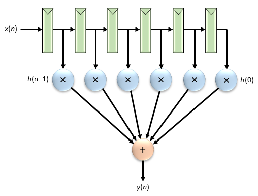
d) [15 pts] Draw a dot diagram showing how the partial products would be
added (include sign extension) for the optimized coefficients you found
in (b), using the FIR architecture shown below and a
6-bit
2's complement input word. Use 4:2, 3:2, and half adders as necessary
and no need to design the final stage carry-propagate adder.
[50 pts] Design of an area-efficient low-pass FIR filter. The filter must meet the following specifications when its sample rate is 100 MHz.
- Passband below 12.0 MHz: no more than 3dB ripple from minimum to maximum levels
- Passband below 18.0 MHz: no more than 3dB attenuation below gain level at DC
- Stopband above 26.0 MHz: at least 16dB attenuation below gain level at DC
- Stopband above 34.0 MHz: at least 27dB attenuation below gain level at DC
- a) [10 pts]
Write a matlab function lpfirstats(H) or
lpfirstats(H,W) that takes a frequency response vector H from
[H,W] = freqz(coeffs) (or a vector of filter coefficients
directly) as an input and returns the four critical values listed above
(passband ripple, etc.).
b) [10 pts] Either by hand or with a matlab function, repeatedly call lpfirstats(H,W) to find a reasonable small area filter. There is no need to write a sophisticated optimization algorithm, just something reasonable that does more than simple coefficient scaling. For example, making small perturbations to the frequency and amplitude values that remez() uses such as using 0.01 and other small values instead of 0.00 in the stopband.
It may be helpful to use the following matlab code. Remember that matlab vectors start at index=1 so H(1) is the magnitude at frequency=0.
       coeffs1   = remez(numtaps-1, freqs, amps);
       coeffs2   = coeffs1*scale;
       coeffs    = round(coeffs2);
       [H,W]     = freqz(coeffs);
       H_norm    = abs(H) ./ abs(H(1));
       [ripple, minpass, maxstoplo, maxstophi] = lpfirstats(H_norm,W);
Assume area is: Total_num_partial_products + 2*Num_filter_taps
Examples from a previous year of the difference between good optimizations and weaker ones--these are class results for ten students for a different filter than the one assigned here:109 area, 31 taps, 47 PPs 109 area, 31 taps, 47 PPs 113 area, 33 taps, 47 PPs 114 area, 33 taps, 48 PPs 123 area, 33 taps, 57 PPs 128 area, 34 taps, 60 PPs 182 area, 55 taps, 72 PPs 221 area, 59 taps, 103 PPs 221 area, 59 taps, 103 PPs 250 area, 61 taps, 128 PPs- c) Provide the following for your smallest-area filter in your paper submission.
i) [5 pts] Filter coefficients
ii) [5 pts] The number of taps, number of required partial products, area estimate, and the attained values for the four filter criteria in dB.
iii) [10 pts] A plot made by: plot_one_lpfir.m (that requires updating) to show the filter's frequency response.
iv) [5 pts] A stem() plot of the filter's coefficients.
d) [5 pts] Include in your submission:
i) Your modified version of plot_one_lpfir.m
ii) Filter coefficients for your smallest-area filter in a copy-and-pasteable matlab vector; for example:
% coeffs.m
coeffs = [1 4 -8 25 -8 4 1];
[40 pts] Design a circuit that multiplies two 4-bit 2's complement inputs and saturates the product to 6 bits. Submit the following:
1) [5 pts] a circuit diagram,
2) [5 pts] calculate the range of the full unsaturated output, and the range of the actual output,
3) [10 pts] a dot diagram,
4) [10 pts] verilog for the design using "*" for the multiplier and "+" for the adder(s),
5) [10 pts] test your verilog design with at least 15 test cases including all extreme input cases, and verify using method ***(1).
———————————————[40 pts] Repeat the previous problem but instead of saturating the output, round it to a 4-bit output using the "add 1/2 LSB and truncate" method. The output may never overflow or underflow.
1,3,4,5) same as the previous problem
2) [5 pts] calculate the range of the full unrounded output, and the range of the actual output,
———————————————[60 pts] Design a complex 2's complement multiplier p = a × b with 4-bit inputs a_r, a_i, b_r, b_i, and 9-bit outputs p_r, p_i. Register all inputs and outputs. Submit the following:
1) [5 pts] a block diagram,
2) [10 pts] a dot diagram,
3) [10 pts] verilog for the design using "*" for the multipliers and "+" for the adders,
5) [35 pts] test your verilog design exhaustively over all 2^16 possible inputs, verifying using the Golden Reference method. State how many errors you have. Submit approximately 100 passing test cases copied & pasted from the most important sections of your exhaustive output, in addition to the required failing case after you purposely make a hardware error: ***(3).