This tutorial describes and provides the code for a starter design that uses a basic method to receive data from a D8M-GPIO 8-megapixel camera connected to the DE1-SoC board through the GPIO interface.
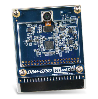
The Terasic D8M-GPIO is an 8-megapixel camera kit with a 2x20 pin GPIO connector interface. It includes a MIPI camera module and a MIPI decoder. The MIPI camera module captures images and sends them out in a MIPI video signal package. This packet is converted into a 10-bit parallel Bayer pattern through a MIPI decoder. The data is transmitted through a 2x20 pin GPIO connector. The MIPI camera module has a built-in Voice Coil Motor (VCM) to control its focal length. Users can adjust the focus via the I2C interface.
Connect an external display to the DE1-SoC board with a standard VGA cable.
Set the monitor's ratio to 4:3 so the image will appear properly proportioned.
Connect the D8M camera to the DE1-SoC board into the outermost GPIO expansion port (GPIO 1) and the camera face toward the outside of the board. Carefully make sure all the pins are secure and inserted fully into the connectors. Make sure the camera is fully pushed into the GPIO expansion slot. It should be a snug fit, be careful not to break the boards by pressing too hard.
Program the DE1-SoC board with the sample project, you should see the camera video on the display.
camera.pdf, overview of the hardware to interface with the camera port
DE1_D8M.v5.zip, verilog source code
Because they are used so often, the top-level module also includes ports for the LED and HEX displays, the SW switches, and the KEY push buttons; as well as very simple code to turn the LED and HEX displays off by default.
Because the VGA display will very often be used when the camera is being used, the VGA port interface is also included in this starter code.
Be sure to use the same clock for the camera and VGA interface.
You may encounter issues with the Lab 5 Starter code compiling the project and then programming the DE1-SOC i.e. failing/succeeding to program and the board not changing or failing to program but the camera output showing on the monitor.
Below are several debugging steps that have had varying levels of success, but a combination of the following should resolve the issues:
Close and reopen the project in Quartus
Power cycle the DE1 SOC may also help here
Connect the DE1 SOC VGA output to a VGA input on a monitor. Using a VGA to HDMI converter may result in no video output.
Power the DE1 SOC off and on while Quartus is still open. Verify the hardware configuration shows a hardware frequency of 24000000 Hz.
Reconfigure the programmer with any of the following steps:
Autodetect the configuration as done in Lab 1
Manually add the correct device and the SOCVHPS device to the programmer flow
Generate a fresh pin assignment file with System Builder and load it into the project. Ensure the D8M camera is selected for GPIO-1. Select the CLOCK, LED, Button, VGA, 7-segment, and Switch boxes.
Restart your computer
camera.zip has some additional logic for the camera output but it is not utilized in the top level so its exact purpose is unclear.
2022/04/11  Written
2022/05/10  Updated camera.zip
2022/05/25  Added first pitfall
2025/02/20  Moved camera.zip to the new Reference section. Added DE1_D8M.v5.zip which was previously used for only Lab 5.
2025/05/28  Added section describing the possible compilation and programming issue

Written by Ziyuan Dong, Derek Li, and Bevan Baas